As core magnetic components in power supply and signal circuits, inductors are prone to degradation failures such as insulation breakdown, magnetic performance attenuation, wire breakage, DC resistance drift and inductance deterioration under long-term high-low temperature, damp heat and energized load conditions due to aging of coil enamel insulation, magnetic cores, pin solder joints and insulating bobbins. Burn-in testing is a key reliability verification method that simulates long-term service degradation of products through accelerated stress to screen out early defects in advance and verify service life stability. Based on types of applied stress, mainstream burn-in tests are divided into six categories: energized load burn-in, temperature cycling burn-in, damp heat burn-in, high-temperature storage burn-in, biased damp heat burn-in and combined mechanical stress burn-in. Each type of test is equipped with standardized processes, stress parameters and judgment indicators, which are elaborated below in combination with universal industrial specifications.
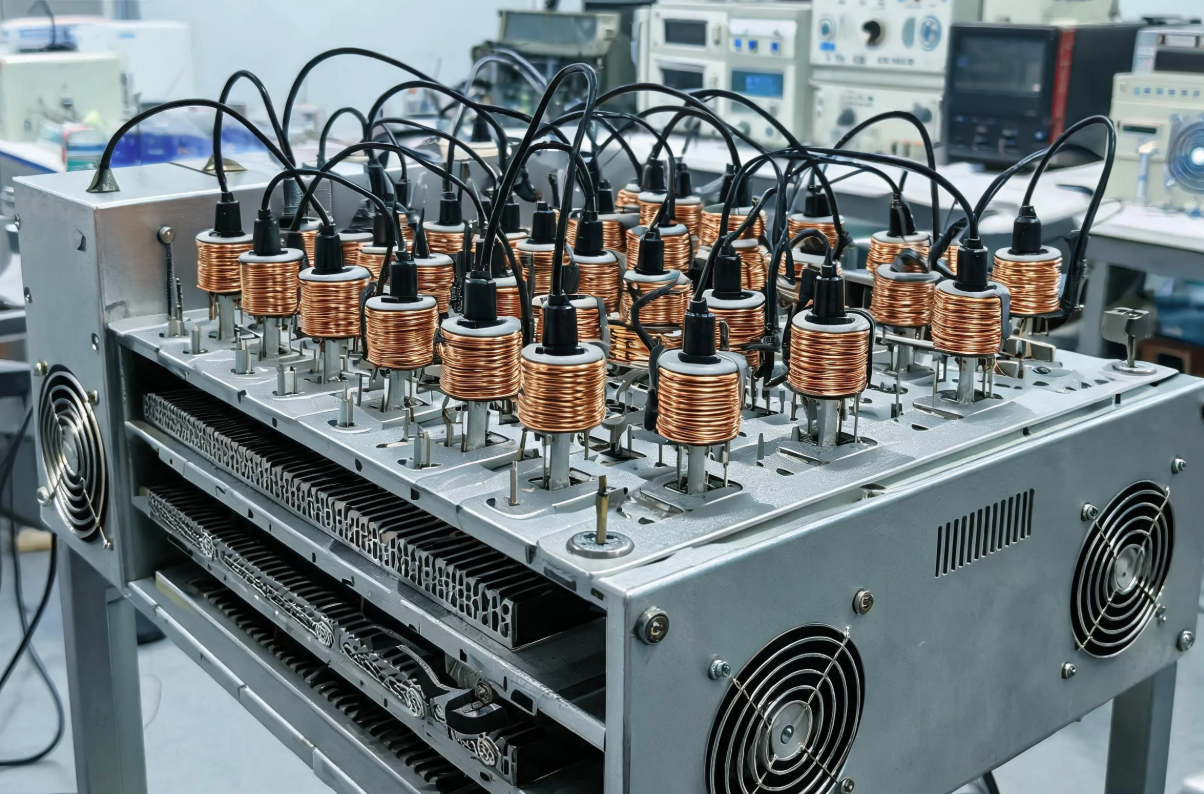
1. Energized Load Burn-in (Electrical Accelerated Burn-in, Core Test Item)
Energized load burn-in simulates the long-term loaded operating state of inductors. By continuously applying rated current and elevating ambient temperature for dual acceleration, it exposes hidden defects including poor coil soldering, pinholes in enameled wires, microcracks inside magnetic cores and weak points of inter-turn winding insulation. It is a mandatory burn-in item for power supply inductors and power inductors.
(1) DC Load Burn-in (Exclusive for Power Inductors)
Place inductors in a constant-temperature oven set to 85℃~125℃ (150℃ for automotive-grade inductors subject to rated operating temperature). Pass 70%~90% of the rated DC saturation current through inductors for continuous energization of 48h to 1000h. Monitor winding DC resistance (DCR) in real time and record a set of data every 24 hours. Failure criteria: A DCR variation exceeding ±3% indicates hidden winding disconnection or cold solder joints; inductance attenuation greater than 5% implies high-temperature demagnetization or internal cracking of magnetic cores. Test principle: Continuous heating generated by energized current superimposed with external high temperature amplifies tiny defects in enamel insulation. Windings with pinholes or thin enamel layers will rapidly suffer inter-turn short circuits, manifested as sharp resistance drop.
(2) AC Ripple Load Burn-in (High-frequency Inductors & Common-mode Inductors)
For high-frequency inductors and filtering common-mode inductors in switching power supplies, compound current of alternating current superimposed on DC bias is adopted to simulate actual circuit ripple stress. Set ambient temperature to 105℃, apply rated DC bias current superimposed on high-frequency AC ripple current with frequency matching the operating frequency of products (tens of kHz to MHz) for 72h continuous operation. Key monitoring indicators include inductance L and equivalent series resistance (ESR). Sustained ESR rise denotes winding insulation aging and increased magnetic core loss; additional balanced impedance detection is conducted for common-mode inductors to avoid filtering failure caused by asymmetric windings.
(3) Pulse Current Burn-in (Automotive & Fast-charging High-power Inductors)
Inductors for new energy and fast charging bear instantaneous large current pulses during operation. Periodic pulse current burn-in is adopted with peak current reaching 1.2 times the rated saturation current at 125℃ ambient temperature for 168h cyclic pulse operation. This test rapidly screens out defects such as poorly sintered magnetic cores and fatigue fracture at winding lead roots. Many inductors qualified under room temperature test will suffer lead fracture or magnetic core cracking after pulse burn-in.
2. High-temperature Storage Burn-in (Stress-free Thermal Aging)
No electrical load is applied in high-temperature storage burn-in. Long-term high temperature alone accelerates material aging, which mainly verifies the high-temperature oxidation resistance of plastic bobbins, insulating tapes, magnetic core coatings and solder joints. It is suitable for pre-screening of chip inductors, molded inductors and chip wound inductors.
Test specifications: Two temperature grades are available: 105℃ for general consumer electronics, 125℃~150℃ for industrial and automotive-grade products. Products are stored statically without energization for 48h to 500h. Compare parameters before and after burn-in: inductance L, DCR, insulation withstand voltage and pin solderability. Common failure phenomena: Resin decomposition of magnetic powder in molded inductors at high temperature leading to sharp inductance drop; softening and deformation of plastic bobbins at high temperature with winding displacement; oxidation of pin pads resulting in breakdown during subsequent withstand voltage test.
Supplementary subdivision: Products shall recover at room temperature for 2 hours before parameter retest after high-temperature storage to eliminate temporary parameter deviation caused by thermal expansion and contraction and avoid misjudgment. This burn-in is often adopted as a pre-process of energized burn-in to eliminate defects of plastics and coatings in advance and reduce failure risks in electrical testing.
3. Temperature Cycling Burn-in (Thermal Stress Burn-in with Alternating Cold & Hot Conditions)
Temperature cycling simulates seasonal temperature differences and cold-hot alternation during equipment startup and shutdown. Periodic mechanical stress generated by thermal expansion and contraction exposes mechanical defects including poor bonding between magnetic cores and windings, microcracks at pin solder joints, bobbin delamination and magnetic core microcracks, serving as a compound reliability burn-in method.
Standard temperature range: -40℃~105℃ for general products, extended to -55℃~125℃ for automotive-grade products. Single cycle flow: Insulation at low temperature for 30min → temperature rise for 15min → insulation at high temperature for 30min → temperature drop for 15min, with a single cycle duration of 90 minutes and total cycles ranging from 100 to 1000. Inductors can be tested under no-load or rated DC current load during the test.
Failure mechanism: Huge difference in thermal expansion coefficients among magnetic cores, copper wires and plastic bobbins generates periodic tension on bonding interfaces under cold-hot alternation, gradually expanding tiny cracks. Appearance inspection (magnetic core chipping, solder joint cracking) and electrical parameter retest shall be implemented after burn-in; leakage current during withstand voltage test or abnormal DCR fluctuation shall be judged as failure. Molded high-current inductors are most sensitive to temperature cycling due to easy delamination between magnetic powder and metal alloy bonding layers, making this test mandatory.
4. Damp Heat Burn-in (Composite Corrosion Aging with Temperature & Humidity)
Damp heat burn-in is divided into constant damp heat and alternating damp heat, simulating humid and dew-forming operating environments to accelerate pin corrosion, water absorption breakdown of winding insulation and hydrolysis aging of enameled wires. It is a mandatory test for outdoor equipment and automotive inductors.
(1) Constant Damp Heat Burn-in
Test conditions: 85℃ / 85%RH, static storage of products without energization for 96h to 1000h. Water vapor slowly penetrates insulation layers, and insulation resistance declines after hydrolysis of enamel wire coating, leading to rusting of metal pins. AC withstand voltage test shall be conducted after burn-in; the product shall be judged as insulation failure if withstand voltage drops below 80% of standard value.
(2) Biased Damp Heat Burn-in (High-accelerated Damp Heat)
Apply rated DC voltage to inductor windings under 85℃ / 85%RH environment. As a high-acceleration aging method, it only takes 24~48 hours to achieve equivalent aging effect of hundreds of hours of conventional damp heat. Micro-current channels formed by water vapor under electrified conditions rapidly expand tiny insulation defects of windings into short circuits, which is used for mass rapid screening of products with low insulation reliability, especially for high-side common-mode inductors in power supplies.
(3) Alternating Damp Heat
Temperature cycling superimposed with humidity variation, ranging from -10℃ to 85℃ with humidity varying from 40% to 95%RH for 200 cycles, simulating dew formation day and night. It targets industrial control inductors for outdoor use to verify the waterproof performance of magnetic core sealing coatings.
5. Combined Stress Accelerated Burn-in (Synchronous Superposition of Multiple Stresses for High-end Products)
Single-stress burn-in only simulates a single failure inducement. High-end automotive-grade and aerospace inductors adopt burn-in with synchronous superposition of multiple stresses including high temperature, current, humidity and vibration to fit actual complex working conditions to the maximum extent and greatly shorten burn-in cycles.
Typical scheme: Place inductors in an 85℃ / 85%RH damp heat chamber, pass rated operating current through inductors and apply random vibration of 10~2000Hz simultaneously for 72h. Three types of degradation including electrical thermal stress, water vapor corrosion and mechanical vibration exist synchronously, which can screen four categories of defects: insulation defects, solder joint failures, magnetic core bonding defects and lead fatigue fractures. Conventional consumer electronics generally do not adopt this method due to high test costs, which is only applied for reliability verification of AEC-Q200 automotive-grade inductors and military inductors.
6. Auxiliary Mechanical Stress Burn-in (Vibration & Shock Burn-in)
Mechanical burn-in is often combined with temperature and energized burn-in as an auxiliary independent aging method to simulate long-term transportation vibration and equipment oscillation.
(1) Random Vibration Burn-in
Triaxial random vibration with acceleration of 10G and frequency of 10~2000Hz for 4h continuous operation, with oven maintained at 85℃ and inductors energized simultaneously. Key inspection items include fatigue fracture at lead roots and pad desoldering of chip inductors.
(2) Shock Burn-in
Half-sine shock with peak acceleration of 500G for 1000 shocks, simulating dropping and instantaneous impact of equipment to verify magnetic core firmness and winding fixing strength.
Visual inspection for magnetic core detachment and lead fracture shall be conducted after burn-in, and DCR retest shall be performed to check abnormal rise.
7. General Judgment Process and Supporting Test Items for All Burn-in Tests
All burn-in tests follow a unified process: Record pre-burn-in parameters (L, DCR, ESR, insulation resistance, withstand voltage) → Apply corresponding stress for burn-in → Recover at room temperature for 2h → Retest electrical parameters → Appearance inspection → Re-inspection of withstand voltage and insulation.
Unified failure judgment thresholds: DC resistance DCR variation > ±3%; inductance L offset > ±5%; insulation resistance drops below 100MΩ; breakdown or leakage occurs during AC withstand voltage test; magnetic core cracking, lead detachment, peeling or oxidation of solder joints on appearance. Products meeting any above condition shall be judged as burn-in failure.
8. Selection Suggestions of Burn-in Schemes for Different Types of Inductors
Molded Power Inductors: Prioritize DC energized load burn-in + temperature cycling burn-in to cover thermal stress and delamination defects caused by thermal expansion and contraction;
Common-mode Filter Inductors: Biased damp heat burn-in + AC ripple load burn-in, focusing on insulation and high-frequency loss performance;
Miniature Chip Wound Inductors: High-temperature storage + constant damp heat to screen defects of plastic bobbins and thin enamel coatings;
Automotive & Military-grade Inductors: Combined multi-stress burn-in + pulse current burn-in to meet stringent service life verification requirements.
Inductor burn-in tests artificially amplify hidden internal defects of components through four types of accelerated stresses: thermal, electrical, humid and mechanical stresses, so as to eliminate early failure products in advance and verify long-term operational stability of products. Energized load burn-in serves as the fundamental core test targeting electrical insulation and winding loss; high-temperature storage focuses on high-temperature resistance of polymer insulating materials; temperature cycling addresses mechanical delamination and cracking induced by thermal expansion and contraction; damp heat series burn-in verifies moisture-proof insulation and corrosion resistance; combined multi-stress burn-in is adopted for in-depth verification of high-reliability scenarios. In actual production and reliability certification, enterprises will combine 2 to 4 burn-in methods according to product application scenarios, matched with standardized parameter monitoring and failure judgment criteria to fully cover long-term aging failure modes of four core structures of inductors: coils, magnetic cores, bobbins and solder joints, ensuring stable parameters and safe operation of mass-produced products throughout the full life cycle.